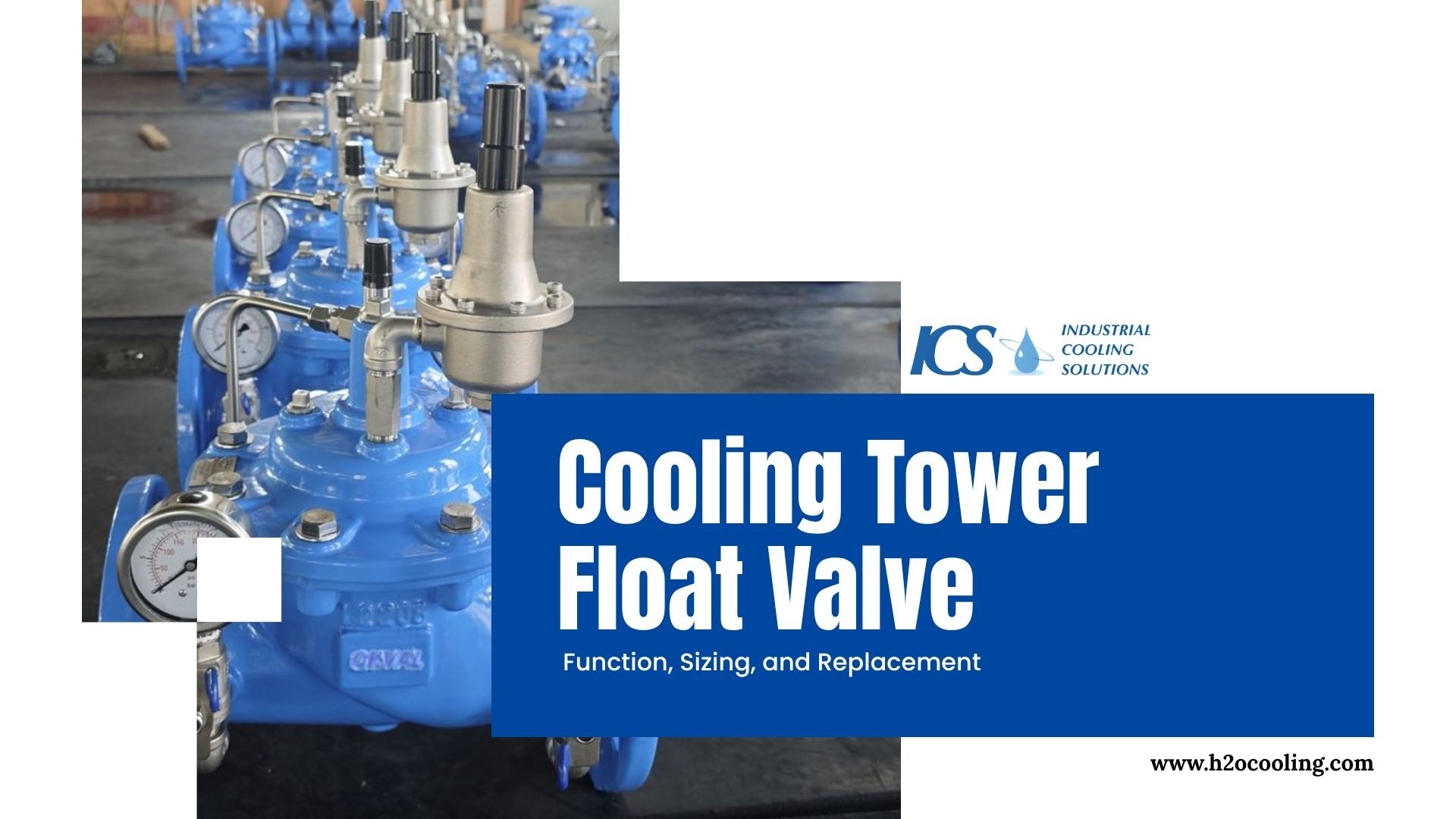
A cooling tower float valve regulates makeup water control by maintaining a stable water level inside the basin as evaporation, drift, and blowdown reduce system volume. The valve operates through a float ball mechanism that opens or closes based on water level changes.
Proper valve sizing is critical to prevent underfilling or overflow issues. Incorrect selection or poor maintenance leads to pump cavitation, water loss, and unstable cooling performance, making float valves a small but essential component in overall system reliability.
What a Cooling Tower Float Valve Actually Controls in System Operation
Industrial facilities rely on precise makeup water control to keep cooling processes running continuously. Continuous water loss from evaporation, drift, and scheduled blowdown demands an automatic refill solution.
The cooling tower float valve provides this solution by acting as a mechanical guardian for the basin.
Role in Makeup Water Control
Facilities lose thousands of gallons of fluid daily through standard evaporative cooling processes. Plant operators cannot manually control refill rates without causing severe system imbalances.
How does a simple mechanical device solve this massive operational challenge? Consider these primary functions:
- The mechanism ensures a constant basin level without requiring human intervention.
- It maintains the system mass balance effectively during peak heat load hours.
- The device prevents the main circulation pumps from running dry and causing seal damage.
- It supports consistent heat transfer by keeping the entire cooling loop fully primed.
Relationship Between Water Level and System Stability
Fluid height dictates the overall stability of your thermal management system. Dropping fluid levels introduces air into the suction lines. Excess fluid causes chemical dilution and environmental waste.
Why is precise fluid height so critical to your operational success? Look at these operational impacts:
- Low levels cause severe pump cavitation and destructive air entrainment.
- High levels lead to continuous overflow and expensive chemical treatment dilution.
- Stable levels guarantee optimized cooling efficiency and predictable thermal performance.
Float Ball Mechanism and Mechanical Operation
The physical working principle of this component relies entirely on buoyancy and leverage. The device requires no electrical power, sensors, or complex automation to function accurately.
How does this pure mechanical action translate into reliable flow regulation? Review these operational mechanics:
- The float ball rises with the fluid surface to push the valve seat closed.
- A dropping fluid surface lowers the arm and pulls the valve seat open.
- Incoming pressure forces fresh supply fluid through the open orifice.
Common Failure Modes That Disrupt Float Valve Performance
Mechanical components operating in harsh industrial environments eventually degrade over time. Facility managers must understand how and why these specific components fail to prevent sudden plant shutdowns.
Mechanical Wear and Float Ball Failure
Constant movement wears down the internal linkage pins and rubber seating gaskets. The buoyant sphere can develop microscopic cracks that allow fluid to enter the hollow chamber. What happens when these structural failures compromise the entire assembly? Watch for these specific consequences:
- Loss of buoyancy causes the arm to remain down and the valve to stay open.
- Constant water inflow overwhelms the basin capacity rapidly.
- The system experiences massive overflow and unacceptable fluid wastage.
Scaling and Debris Interference
Cooling loops accumulate dissolved solids, airborne dirt, and biological growth over time. These contaminants concentrate in the basin and attach to submerged mechanical linkages. Consider these common interference issues:
- Calcium carbonate scaling builds up heavily on the brass linkage arms.
- Solid debris restricts the physical movement of the pivot points.
- Heavy contamination causes the internal plunger to stick in a partially open position.
Incorrect Valve Sizing Impact
Engineers make severe design mistakes when they guess the required flow capacity. Selecting the wrong orifice size destroys system stability faster than mechanical wear. Analyze these sizing-related failures:
- An undersized unit refills the basin too slowly during peak evaporative loads.
- Slow refill rates cause the basin to drop below the minimum pump suction requirement.
- An oversized unit blasts too much flow into the basin and causes constant overflow tripping.
How to Size a Cooling Tower Float Valve Correctly
To accurately size a Cooling Tower Valve, engineers must mathematically calculate the total system demand. Guessing the flow rate, instead of performing the proper calculations, leads directly to the failure modes discussed previously.
Key Parameters Required for Valve Sizing
You must evaluate four specific operational metrics to determine the true makeup demand. Missing just one of these metrics results in an underperforming refill system. What exact numbers do you need to calculate the correct capacity? Gather these critical data points:
- The exact volume of evaporation loss is based on the maximum heat load.
- The scheduled blowdown requirement is needed to control dissolved solids cycles.
- The estimated drift losses escaping through the top of the exhaust fans.
- The peak load variations occur during mid-summer operating conditions.
Makeup Water Flow Rate Estimation Logic
Industrial engineers use a standardized formula to estimate the maximum refill demand. The formula accounts for temperature differentials and total recirculation rates. How do system variables change the final mathematical requirement? Review these estimation principles:
- Higher ambient temperatures create higher evaporation rates and require more refill flow.
- A larger overall system volume dictates a higher baseline refill demand.
- Sudden load fluctuations require the orifice to handle brief periods of extreme flow.
Matching Valve Capacity to System Demand
You must select an orifice that delivers the calculated flow rate at the available supply pressure. Manufacturers provide specific flow charts linking inlet pressure to gallons per minute.
Why is matching this specific capacity strictly mandatory for continuous operation? Consider these operational requirements:
- Correct capacity avoids delayed refill cycles during sudden thermal load spikes.
- Proper sizing prevents unstable fluid levels that trigger low-level alarms.
- Accurate flow matching maintains continuous operation without manual bypass intervention.
Material Selection for Long-Term Performance
Water chemistry dictates the lifespan of your mechanical hardware. Aggressive chemical treatments and high chloride levels destroy standard brass components rapidly. How do you choose the right construction material for your specific site conditions? Evaluate these material trade-offs:
- Stainless steel provides maximum corrosion resistance for aggressive chemical environments.
- Industrial plastic offers a cost-effective solution but lacks long-term structural durability.
- Standard brass remains common but requires a soft fluid to prevent heavy scaling.
Float Valve vs Electronic Level Control Systems
Facility upgrades often force engineers to choose between mechanical devices and modern electronic sensors. Both technologies offer distinct advantages depending on the specific application requirements. Understanding the fundamental differences ensures you allocate your capital budget wisely.
Functional Comparison Overview
Mechanical devices rely on physical buoyancy, whereas electronic systems use conductivity probes or ultrasonic sensors. Electronic controllers send signals to a motorized actuator or solenoid to start the flow.
Performance Comparison Table
| Parameter | Float Valve | Ultrasonic Sensor | Conductivity Probes | Engineering Insight |
| Control Type | Mechanical | Non-contact Electronic | Contact Electronic | Electronics provide higher precision data. |
| Reliability | High | Medium | Medium | Mechanical systems survive harsh environments better. |
| Maintenance | Low | High | Medium-High | Sensors require frequent calibration and cleaning. |
| Cost | Low | High | Medium | Float valves are highly cost-effective solutions. |
| Accuracy | Moderate | Very High | High | Extreme precision is needed only in critical systems. |
When to Use Float Valves
When it comes to basic commercial and industrial cooling loops, the mechanical cooling tower float valve remains the undisputed standard. Its simple design makes it completely immune to power outages and electronic interference, ensuring reliable operation.
Where do these mechanical workhorses provide the best return on investment? Deploy them in these specific scenarios:
- Standard industrial cooling towers requiring simple and reliable refill operations.
- Harsh operating environments that destroy sensitive electronic circuit boards.
- Remote facilities that demand low-maintenance systems without specialized calibration requirements.
When to Avoid Float Valves
Certain advanced manufacturing processes require fluid control precision down to the millimeter. Mechanical devices lack the tight tolerances required for highly sensitive thermal loops. When should you abandon mechanical simplicity for electronic complexity? Avoid mechanical units in these situations:
- High precision process control applications involving pharmaceutical or semiconductor manufacturing.
- Fully automated facilities that integrate all hardware into a central supervisory control system.
- Smart monitoring environments require constant data logging of makeup flow rates.
Replacement Strategy: When and How to Replace a Float Valve
Waiting for a mechanical device like a Cooling Tower Float Valve to completely fail guarantees a catastrophic plant event. Smart maintenance programs dictate replacing components before they cause emergency downtime.
Signs That Replacement Is Required
Visual inspection provides immediate clues regarding the health of your mechanical linkage. Do not ignore small drips or jerky movements during operation. What physical symptoms indicate an immediate need for component replacement? Watch for these severe warning signs:
- Continuous overflow occurs even when the cooling demand remains exceptionally low.
- Fluctuating fluid levels that trigger the main circulation pump alarms constantly.
- Visible corrosion is eating away at the main pivot pin and lever arm..
Step-by-Step Replacement Process
Swapping the cooling tower float valve hardware requires proper isolation and basic plumbing skills. Rushing the process often results in stripped threads and subsequent leaks.
How do you execute a perfect replacement without causing additional system issues? Follow this exact sequence:
- Shut off the water: Close the main makeup supply line and check that the pressure is at zero.
- Lower the water level: Drain some of the basin's fluid so you can easily see and access the mounting connection.
- Remove the old hardware: Carefully unscrew the existing unit, taking care not to strip or damage the supply pipe's threads.
- Install the new unit: Apply thread sealant to the new hardware and screw it in, making sure it's at the same horizontal angle as the old one.
- Turn the water back on: Slowly restore the supply pressure and test the new unit by manually moving the arm to check its mechanical operation.
Conclusion
A cooling tower float valve plays a critical role in maintaining makeup water control and stable water level conditions, directly influencing system reliability and performance. While the mechanism is simple, incorrect valve sizing, poor maintenance, or improper installation can lead to overflow, pump damage, and operational instability.
Engineers must focus on accurate demand calculation, proper material selection, and regular inspection to ensure long-term performance. A well-selected float valve supports efficient cooling operation and prevents costly system failures.
Frequently Asked Questions
What does a cooling tower float valve do?
A cooling tower float valve regulates makeup fluid flow to maintain a consistent basin height. It automatically opens or closes based on fluid height changes caused by evaporation and system losses. This essential component ensures stable thermal operation and prevents both basin overflow and expensive pump damage.
How do you size a float valve for a cooling tower?
Sizing depends heavily on the total makeup demand, including evaporation, blowdown, and drift losses. Engineers must calculate the peak flow requirements based on maximum summer heat loads. You must select a specific capacity that meets demand rapidly without causing instability or overflow issues.
Why do float valves fail in cooling towers?
These devices fail primarily due to mechanical wear, severe scaling, debris blockage, or incorrect sizing. Mineral deposits lock the pivot joints, while hollow spheres develop cracks and lose vital buoyancy. These issues reduce physical responsiveness and cause either continuous fluid flow or insufficient basin refill.
Can float valves be replaced with electronic systems?
Yes, advanced electronic level controllers can replace mechanical hardware in high-precision manufacturing systems. Electronics provide superior data logging and exact precision for automated facilities. However, mechanical devices remain much more reliable and cost-effective in harsh industrial environments where simplicity works best.
How often should a cooling tower float valve be inspected?
Operators should inspect these critical components at least once a month in standard industrial systems. Regular cleaning and checking for linkage wear or mineral scaling prevents sudden failure. This basic preventive maintenance ensures consistent operation and protects the main circulation pumps from running dry.