Cooling tower pump cavitation is a silent destroyer in industrial systems. It begins subtly but can lead to catastrophic equipment failure, costly downtime, and efficiency losses that ripple through an entire operation. Understanding the mechanics behind this phenomenon is the first step toward safeguarding your equipment.
This guide provides a deep dive into diagnosing and preventing cavitation issues. You will learn the specific causes, how to detect early warning signs, and the engineering principles required to maintain optimal NPSH requirements.
Whether you are troubleshooting suction pressure problems or designing a new system, this article serves as your blueprint for cavitation prevention.
What Is Cavitation in Cooling Tower Pumps?
Cavitation describes the formation and subsequent collapse of vapor cavities within a liquid. In a cooling tower pump, this happens when the local pressure of the water drops below its vapor pressure. The water essentially boils at ambient temperature, creating small bubbles of vapor.
These bubbles travel to areas of higher pressure within the pump, such as the impeller vanes. When they reach this high-pressure zone, they collapse or implode violently. This implosion creates a shockwave that blasts small pieces of metal off the impeller, leading to pitting.
Here’s how to distinguish between the two main types of cavitation:
- Suction cavitation: Bubbles form at the eye of the impeller where pressure is low.
- Discharge cavitation: Bubbles form at the tip of the impeller where discharge pressure is extremely high.
Both types of cavitation can reduce the pump's flow and head, causing it to operate outside its ideal performance curve.
Why Cavitation Happens | Root Causes
Cavitation does not happen randomly; it is always a symptom of an underlying hydraulic or mechanical issue. Identifying the root cause requires a systematic look at pressure, flow, and design.
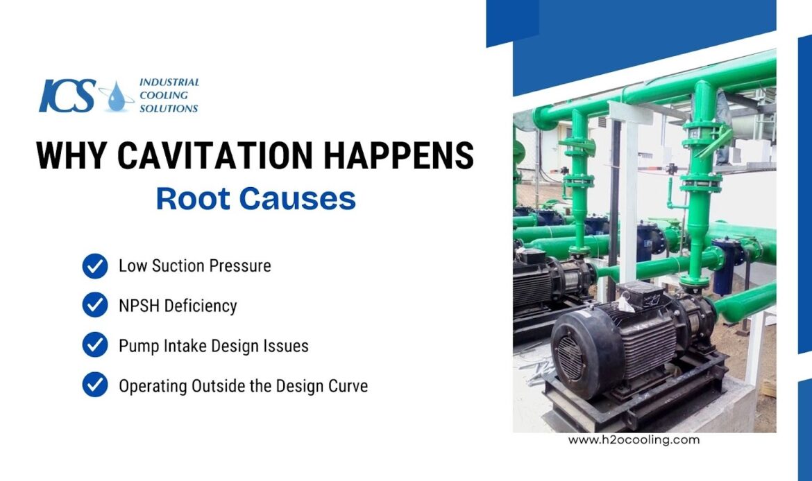
Low Suction Pressure (Primary Cause)
Low suction pressure is the most common culprit in cooling tower applications. The pump must receive liquid at a pressure higher than the vapor pressure of the fluid to prevent boiling.
Several factors can lead to suction pressure problems that trigger cavitation:
- Clogged Suction Strainers: Debris restricts flow, causing a massive pressure drop before the fluid reaches the impeller.
- Low Basin Water Level: If the water level in the cooling tower basin drops, the static head pressure available to the pump decreases.
- High Fluid Temperature: Warmer water has a higher vapor pressure, meaning it boils more easily, requiring higher suction pressure to remain liquid.
NPSH Deficiency
Net Positive Suction Head (NPSH) is the fundamental concept in pump hydraulics. It defines the energy available to the fluid to prevent vaporization.
Engineers must understand the critical balance between two specific NPSH values:
- NPSH Available (NPSHa): This is the absolute pressure at the suction port of the pump, minus the vapor pressure of the liquid. It is a function of the system design.
- NPSH Required (NPSHr): This is the minimum pressure required by the pump itself to operate without cavitating.
Pump Intake Design Issues
Even with correct calculations, physical design flaws can disrupt the flow profile entering the pump. A pump requires a uniform velocity distribution at the impeller eye to function correctly.
Poor pump intake design often introduces turbulence that mimics low-pressure conditions:
- Sharp Elbows: Installing an elbow directly on the pump suction flange creates uneven flow and swirling.
- Inadequate Submergence: If the intake pipe is not submerged deeply enough in the basin, it can draw air from the surface (vortexing).
- Improper Piping Size: Undersized suction piping increases friction losses, directly reducing the available pressure at the pump inlet.
Operating Outside Design Curve
Pumps are designed to operate efficiently at a specific flow rate and head, known as the Best Efficiency Point (BEP). Deviating too far from this point invites trouble.
Running a pump far to the right or left of its curve changes internal velocities and pressures:
- High Flow (Runout): Operating at flow rates higher than design increases NPSH requirements, often exceeding what the system can provide.
- Low Flow (Recirculation): Operating at very low flows causes internal recirculation at the impeller eye, creating localized low-pressure zones and cavitation.
How to Diagnose Cavitation
Detecting cavitation early can save thousands of dollars in impeller replacements and casing repairs. The signs are often audible, like a distinct rattling or crackling sound, and physical, such as unusual vibrations.
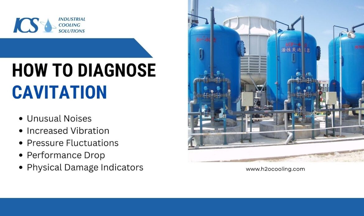
Left unchecked, cavitation can severely impact the efficiency and lifespan of your equipment.
Unusual Noises (Rumbling, Grumbling)
The most distinct sign of cavitation is sound. It is often described as pumping gravel or marbles. This noise is the sound of vapor bubbles imploding near the impeller surface.
Vibration Increase
Cavitation creates unstable flow patterns and mechanical shockwaves. These forces transfer directly to the pump housing and bearings.
You will observe a spike in vibration levels that corresponds with the noise. Routine vibration analysis reveals random, high-frequency energy spikes. These vibrations accelerate bearing wear and loosen mechanical seals.
Pressure Fluctuations
A stable pump should have a steady discharge gauge reading. Cavitation causes the flow to become erratic.
Watch for these indicators on your gauges:
- Oscillating Discharge Pressure: The needle on the discharge gauge bounces or fluctuates widely rather than holding steady.
- Erratic Suction Vacuum: The suction gauge may show unstable readings as vapor pockets form and collapse.
Performance Drop
When bubbles take up space in the liquid, the pump moves less water. The overall efficiency of the system plummets.
Operators will notice a reduction in flow rate or discharge pressure even though the pump speed remains constant. The pump consumes energy to create shockwaves rather than moving fluid, destroying efficiency.
Physical Damage
If you open the pump for inspection, the evidence of cavitation is undeniable. Look for these specific damage patterns on internal components:
- Pitting: The metal surface of the impeller vanes looks like a sponge or Swiss cheese.
- Erosion: Material is stripped away from the casing or wear plates.
The Engineering Behind Cavitation
Preventing cavitation requires more than guesswork; it demands precise calculation. Engineers use specific formulas to ensure the system pressure at the pump inlet always exceeds the liquid's vapor pressure.
NPSH Calculation Basics
Calculating Net Positive Suction Head Available (NPSHa) is the first step in system verification.
The standard formula considers atmospheric pressure, static head, friction losses, and vapor pressure:
NPSHa = Absolute Pressure + Static Head – Friction Loss – Vapor Pressure
NPSHa = H_{abs} + H_{s} - H_{f} - H_{vp}
Where:
- H_abs = Absolute pressure on the surface of the liquid.
- H_s = Static height of the liquid above the pump centerline.
- H_f = Friction losses in the suction piping.
- H_vp = Vapor pressure of the liquid at the operating temperature.
Cavitation vs Air Entrapment vs Flashing
These issues are often confused, but are not identical.
| Condition | Cause | Damage Pattern |
| Cavitation | Low suction pressure | Impeller pitting & vibration |
| Air Entrainment | Air is drawn into the suction | Noise, unstable flow |
| Flashing | Liquid permanently vaporizes | Severe erosion |
As cooling tower water temperature increases, vapor pressure rises, reducing NPSHa.
Always calculate NPSHa using the maximum expected operating temperature to ensure worst-case reliability.
Prevention Techniques
Once you understand the math and the symptoms, you can implement strategies to stop cavitation before it starts. Cavitation prevention relies on increasing the pressure available at the pump inlet.
Increase Suction Pressure
Raising the pressure on the suction side is the most direct way to increase NPSHa. By ensuring the pressure of the fluid entering the pump is well above its vapor pressure, you create a larger safety margin against the formation of damaging vapor bubbles.
This can be achieved through various system modifications, each contributing to a more stable and efficient pumping operation.
Consider these physical adjustments to the system:
- Raise Basin Level: Increasing the water level in the cooling tower basin adds static head pressure.
- Clean Strainers: Regularly removing debris reduces friction losses and restores pressure.
Optimize Pump Intake Design
Fluid needs a smooth path to enter the pump without turbulence, as turbulence can reduce efficiency and increase wear on the pump. To stabilize the flow, consider using streamlined inlet designs, such as gradually tapered pipes or flow straighteners, to reduce abrupt changes in velocity.
- Install a straight run of pipe before the suction flange, typically 5 to 10 times the pipe diameter.
- Ensure the pump intake design minimizes sharp turns and complex fittings.
Ensure Adequate NPSHa
If physical changes to the piping are impractical, adjusting system parameters can also be an effective strategy. Altering operational settings can significantly improve the (NPSHa) without costly infrastructure modifications.
These adjustments focus on changing the fluid's properties or the system's pressure to create a more favorable environment for the pump.
You can improve the NPSH margin through operational changes:
- Lower Fluid Temperature: Increasing cooling tower fan speed can lower water temperature, reducing vapor pressure.
- Booster Pumps: In severe cases, installing a low-head booster pump upstream can pressurize the inlet of the main pump.
- Optimize Flow Rate: Adjust flow rates to match system requirements, ensuring efficient operation without overloading the pump.
Adjust Operating Point
Pumps should run where they were designed to run to ensure optimal performance and longevity. Operating pumps outside their intended range can lead to inefficiency, increased energy consumption, and potential damage to the equipment.
Review your system control to keep the pump healthy:
- Throttle Discharge: Slightly closing the discharge valve increases backpressure, moving the operating point back toward the left on the curve (if the pump is running out).
- Variable Frequency Drives (VFDs): Slowing the pump down reduces the NPSHr significantly, often solving cavitation issues instantly.
Use Anti-Cavitation Impellers
If software-based solutions aren't enough, some manufacturers offer specialized hardware to combat cavitation. These are particularly useful when system-wide changes are impractical or too expensive.
These hardware modifications focus on altering the pump's internal hydraulics to better withstand low-pressure conditions.
Modifying the impeller can sometimes help handle difficult conditions:
- Inducers: A small axial flow impeller added to the pump's suction eye to increase pressure before it reaches the main impeller.
- Larger Eye Area: Using an impeller with a bigger suction eye reduces the speed of fluid entering the pump, which lowers the Net Positive Suction Head required (NPSHr).
- Slow Pump Speed: Reducing the speed of the pump decreases the pressure drop, making it easier for fluid to flow and reducing NPSHr.
Cost & Consequences of Ignoring Cavitation
Ignoring the warning signs of cooling tower pump cavitation is a financial risk. The cost of intervention is always lower than the cost of failure.
Letting cavitation persist leads to severe operational penalties:
- Reduced Lifespan: An impeller designed to last 10 years can be destroyed in six months.
- Energy Waste: A cavitating pump moves less fluid while consuming the same or more power.
- Seal and Bearing Failure: The vibration caused by cavitation destroys mechanical seals and bearings, leading to leaks and seizures.
- Production Downtime: An unexpected pump failure can shut down the entire cooling loop, halting production.
Conclusion
Cooling tower pump cavitation is a preventable problem that requires vigilance and engineering knowledge. By understanding the relationship between pressure, temperature, and flow, you can diagnose issues before they destroy your equipment.
Remember that cavitation prevention is a combination of smart pump intake design, regular maintenance, and monitoring. Whether you are addressing suction pressure problems or calculating NPSH requirements, the goal remains the same: keep the pressure high enough to keep the fluid liquid.
Protecting your pumps ensures process reliability and safeguards your bottom line. Want to maintain peak performance or upgrade with premium parts? Contact us today at ICS for expert cooling tower maintenance and high-quality solutions!
Frequently Asked Questions
What is cooling tower pump cavitation?
Cooling tower pump cavitation is the formation and collapse of vapor bubbles inside the pump. It occurs when liquid pressure drops below vapor pressure, causing pitting damage, noise, and vibration.
How does NPSH relate to cavitation?
NPSH (Net Positive Suction Head) measures the pressure available to prevent boiling. If NPSH Available (NPSHa) is lower than NPSH Required (NPSHr), the fluid vaporizes, and cavitation occurs.
What are the warning signs of cavitation?
Common signs include loud noises sounding like gravel pumping, excessive vibration, and fluctuating discharge pressure. You may also notice a drop in flow rate or pump efficiency.
How can cavitation be prevented in pumps?
Prevent cavitation by ensuring NPSH requirements are met through proper design and operation. Keep suction strainers clean, maintain basin water levels, and ensure the pump operates near its best efficiency point.
Why does suction pressure affect cavitation?
Suction pressure determines if the fluid remains liquid or turns to vapor. Low suction pressure allows the fluid to boil at the impeller eye, which is the primary cause of cavitation bubbles.