

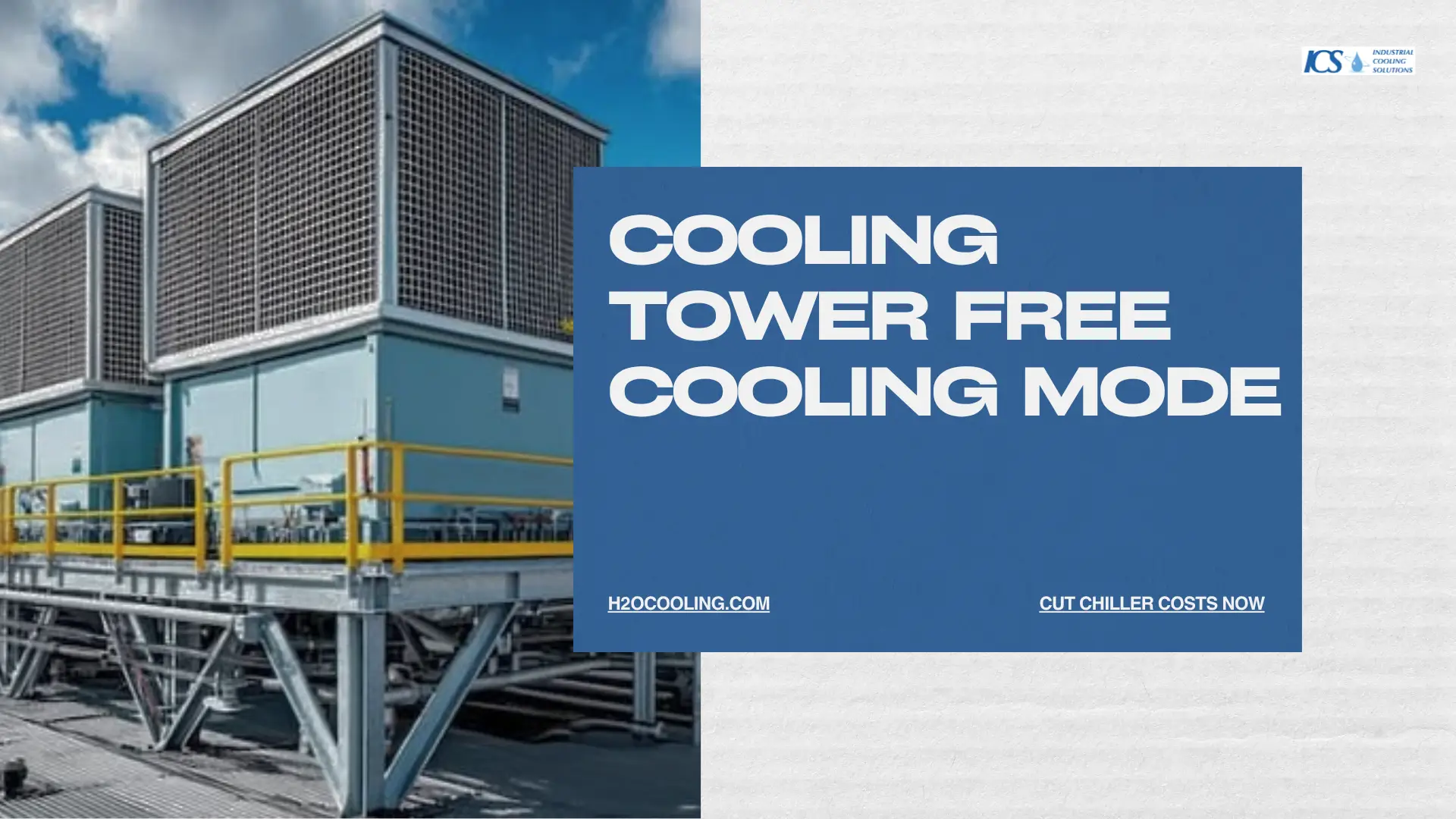
Cooling tower free cooling mode uses cold ambient air to chill water through a cooling tower and heat exchanger, bypassing the chiller compressor entirely. When the outdoor wet-bulb temperature drops low enough, the system delivers chilled water with only pump and fan energy, cutting compressor power by up to 70% during winter and shoulder seasons.
Mechanical cooling is expensive. The compressor in a water-cooled chiller draws the largest share of plant energy. Yet for many hours each year, the outdoor air is already cold enough to do that work for free.
Cooling tower free cooling captures those hours. It is a proven strategy that shifts the cooling load away from the compressor and onto the cooling tower. The savings are significant, and codes like ASHRAE 90.1 now mandate the approach in many climates.
1. The Thermodynamics of Free Cooling: Bypassing the Compressor
Defining the Waterside Economizer
A waterside economizer is a piping and control arrangement that produces chilled water without running the chiller compressor. The cooling tower rejects heat to the atmosphere. A heat exchanger then transfers that cooling to the building loop.
The compressor sits idle. Only pumps and tower fans consume power.
The Real Energy Shift
Free cooling does not eliminate all energy use. It relocates the load.
- The chiller compressor switches off.
- Condenser water pumps continue to circulate.
- Cooling tower fans keep rejecting heat.
- A small approach penalty appears at the heat exchanger.
The net result favors the operator. A compressor might draw 0.6 kW per ton under design conditions. Free cooling can reduce plant input to roughly 0.1-0.2 kW per ton, since fans and pumps replace mechanical refrigeration.
The Wet-Bulb Threshold Rule
Outdoor wet-bulb temperature governs everything. The cooling tower can only approach the ambient wet-bulb, never beat it.
To deliver chilled water at a useful temperature, the wet-bulb must sit below the chilled-water setpoint by a margin large enough to cover two approach penalties—one at the tower, one at the heat exchanger. This wet-bulb threshold defines when economizer mode becomes viable.
2. The Core Mechanical Configurations Matrix
Three distinct methods deliver free cooling. Each suits a different plant layout and risk profile.
| Economizer Configuration | Mechanical Interface Mechanism | Chiller Operational State | Primary Engineering Trade-Off / Risk |
| Indirect Plate Heat Exchanger (PHE) | Corrugated stainless-steel plates transfer heat across two isolated fluid streams | Fully offline (non-integrated) or throttled down (integrated series) | Safest design; isolates building loop from tower water; adds hydraulic pressure drop and approach penalty |
| Direct Strainer Cycle (Chiller Bypass) | Tower basin water is filtered and pumped directly into the building's chilled-water loop | Completely shut down; fluid physically bypasses the evaporator shell | Lowest capital cost; highest risk of piping corrosion, coil fouling, and biological contamination |
| Refrigeration Migration (Thermosiphon) | Natural refrigerant vapor migrates toward the colder condenser shell via gravity-driven pressure difference | Compressor fully offline; expansion valves locked open | Minimal mechanical space required; limited to 30–40% of design cooling capacity |
Indirect Plate Heat Exchanger (PHE)
The plate heat exchanger is the most common configuration. It places a barrier between the open tower loop and the closed building loop.
- Condenser water flows on one side of the plates.
- Building chilled water flows, on the other hand.
- The two streams never mix.
This separation protects the clean-building loop from contamination by tower water. The trade-off is an added approach temperature across the plates, typically 2°F to 4°F.
Direct Strainer Cycle (Chiller Bypass)
The strainer cycle pipes cold tower water directly into the chilled-water loop. A strainer removes debris before the water reaches building equipment.
This method skips the heat exchanger penalty, so it offers the warmest possible switch-over point. The risk is contamination. Open tower water carries dirt, biological matter, and minerals into coils and valves.
Use the strainer cycle only where water quality is tightly controlled.
Refrigeration Migration (Thermosiphon)
Thermosiphon free cooling uses the chiller's own refrigerant. When the condenser runs colder than the evaporator, refrigerant migrates naturally and carries heat without the compressor.
- No compressor operation occurs.
- Refrigerant circulates by natural pressure difference.
- A large crossover pipe links the evaporator and the condenser.
This option keeps the existing chiller shell in service and avoids a separate heat exchanger. It demands a chiller built or retrofitted for the function.
3. System Architecture: Integrated Series vs. Non-Integrated Parallel Logic
How the economizer ties into the chiller plant determines how many free-cooling hours you actually capture.
Non-Integrated Parallel Economizers
A non-integrated economizer operates as an all-or-nothing device. It runs either the chiller or the free-cooling path, never both.
- When the wet-bulb is cold enough, free cooling carries the full load.
- When it is not, the chiller takes over completely.
- Partial free cooling is impossible.
This design is simpler and cheaper. It also wastes the many shoulder-season hours when free cooling could handle part of the load.
Integrated Series Economizers (The ASHRAE 90.1 Mandate)
An integrated economizer pipes the heat exchanger in series, ahead of the chiller. It pre-cools the return water before the chiller finishes the job.
This captures partial free cooling across a much wider range of conditions. The economizer trims the load whenever the air is even slightly favorable.
ASHRAE 90.1 requires integrated fluid economizers in most applications. The standard mandates that economizer systems integrate with mechanical cooling and provide partial cooling, precisely because parallel designs leave so much energy on the table.
4. Calculating the Dual-Approach Switch-Over Threshold
The switch-over point depends on two stacked penalties. Both must be added to the wet-bulb before you know the achievable supply temperature.
The Cooling Tower Approach Constraint
The cooling tower cannot produce water colder than the wet-bulb temperature. The gap between leaving water and wet-bulb is the tower approach.
If a tower produces 85°F water at a 78°F wet-bulb, the approach is 7°F. Colder ambient air narrows this gap and improves performance.
The Heat Exchanger Approach Constraint
The plate heat exchanger adds a second penalty. Building water leaves the exchanger warmer than the tower water entering it.
A typical heat exchanger approach runs 2°F to 4°F. Add this to the tower approach to find the minimum achievable chilled-water temperature for a given wet-bulb.
Example stack:
- Outdoor wet-bulb: 45°F
- Tower approach: 7°F → tower water at 52°F
- Heat exchanger approach: 3°F → chilled water at 55°F
If the building setpoint is 55°F or higher, full free cooling is possible.
Automation & Telemetry Placement
Reliable switch-over needs accurate sensing. Place wet-bulb sensors where they read true ambient conditions, away from tower discharge plumes.
- Monitor the outdoor wet-bulb continuously.
- Track condenser and chilled-water temperatures.
- Program a deadband to prevent rapid cycling between modes.
- Stage the transition so pumps and valves move in sequence.
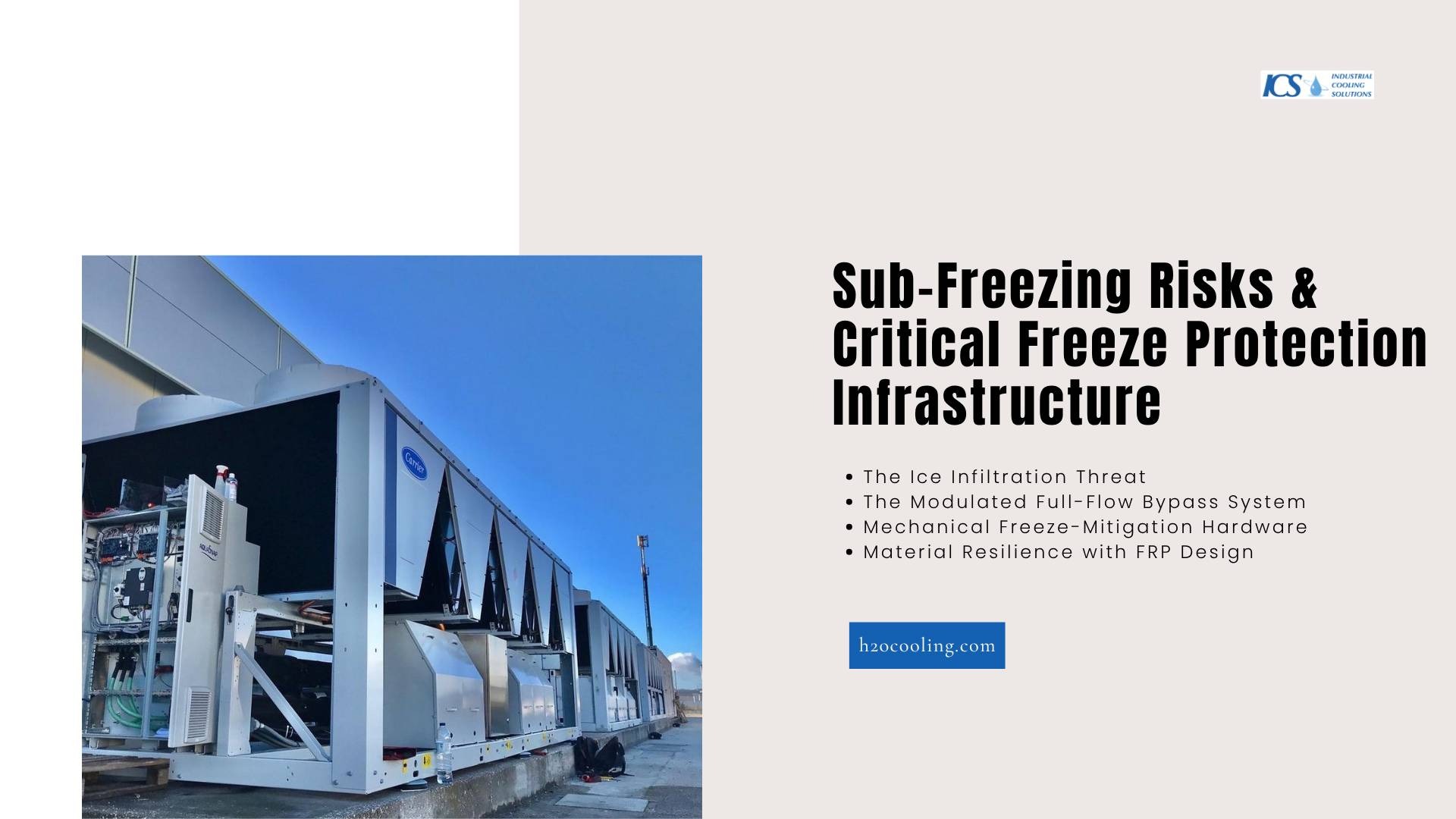
5. Sub-Freezing Risks & Critical Freeze Protection Infrastructure
Free cooling runs hardest in winter. Cold weather delivers the savings and introduces the danger.
The Ice Infiltration Threat
Water near freezing can form ice inside the tower fill, basin, and piping. Ice blocks flow, damage components, and can collapse fill packs.
A frozen tower fails when you need it most. Freeze protection is not optional in cold climates.
The Modulated Full-Flow Bypass System
A full-flow bypass keeps water moving and warm. Instead of spraying water over a cold tower, the system routes flow through a bypass line below the fill.
- The bypass maintains circulation.
- It blends warm return water to hold the basin temperature.
- Control valves modulate flow to match the freeze risk.
Moving water resists freezing far better than still water.
Mechanical Freeze-Mitigation Hardware
Several hardware measures work together to prevent ice damage:
- Electric basin immersion heaters keep standing basin water above freezing during low-load or off cycles.
- Vibration isolation interlocks detect ice buildup on fans and shut the unit down before mechanical damage occurs.
- Timed fan reversal sequences run fans briefly in reverse to melt ice forming on louvers and inlet surfaces.
Material Resilience with FRP Design
Fiberglass-reinforced plastic resists the freeze-thaw cycle. FRP material does not corrode, and it tolerates thermal stress better than coated steel.
Towers built with FRP components hold up through repeated winter operation, reducing maintenance and extending service life.
6. Water Quality, Filtration, and Biological Asset Protection
Cold water does not mean clean water. Free cooling brings its own contamination concerns.
The Cold Water Biological Illusion
Operators often assume winter water carries no biological risk. That assumption is false.
Many organisms slow down in cold water but survive. When the plant returns to warmer operation, surviving colonies multiply rapidly. The transition seasons carry real Legionella risk.
Protecting Heat Exchanger Plates from Biofilms
Biofilm coats heat exchanger plates and destroys thermal performance. A thin biological layer raises the approach temperature and erases free-cooling savings.
- Maintain consistent chemical treatment year-round.
- Filter condenser water to remove suspended solids.
- Inspect plates on a regular schedule.
Adapting the Compliance Framework (ASHRAE 188-2021)
ASHRAE 188-2021 requires a written water management plan for building water systems. Free-cooling operation must fit inside that plan.
Address winter operation, transition-season startup, and the amplification window when the plant returns to mechanical cooling. Assign responsibility, document controls, and audit results.
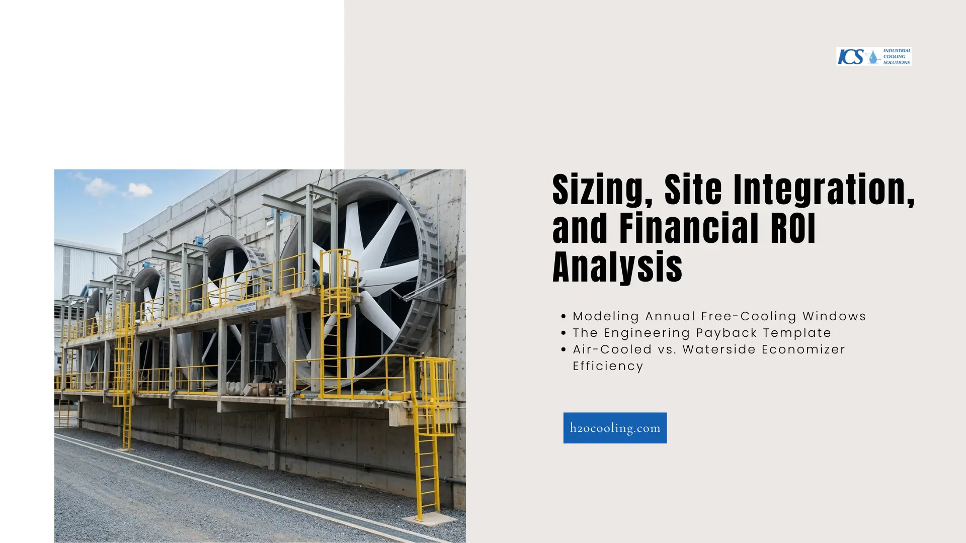
7. Sizing, Site Integration, and Financial ROI Analysis
The business case rests on hours of operation and the value of avoided compressor energy.
Modeling Annual Free-Cooling Windows
Start with local weather data. Count the annual hours below your calculated wet-bulb threshold.
- Pull bin weather data for the site.
- Apply the dual-approach stack to find the threshold wet-bulb.
- Sum the hours below that threshold for full and partial free cooling.
Cold and dry climates yield thousands of free-cooling hours. Hot and humid sites yield fewer, though shoulder seasons still deliver value.
The Engineering Payback Template
A simple payback model compares saved energy against the installed cost.
- Calculate the voided compressor kWh across the annual free-cooling hours.
- Multiply by the local electricity rate to find annual savings.
- Add fan and pump energy as an offset.
- Divide the installed cost of the economizer by net annual savings.
Integrated series systems usually pay back faster because they harvest partial free cooling hours that parallel designs ignore.
Air-Cooled vs. Waterside Economizer Efficiency
Air-cooled economizers depend on dry-bulb temperature. Waterside economizers depend on wet-bulb, which sits lower.
This difference matters. A waterside economizer engages at higher ambient temperatures than an air-side equivalent, extending the free-cooling season and improving overall plant efficiency.
Put Free Cooling to Work in Your Plant
Cooling tower free cooling mode delivers real, measurable savings if the system is sized, configured, and protected correctly. The thresholds, configurations, and freeze defenses in this guide form the foundation. The next step is matching them to your climate, your load, and your existing plant.
International Cooling Solutions designs free-cooling systems that capture maximum savings while safeguarding against freeze and biological risk. Our engineers model your hours, size your economizer, and specify the right freeze protection for your site.
Frequently Asked Questions
What is cooling tower free cooling mode?
Cooling tower free cooling mode is a waterside economizer strategy that uses cool ambient wet bulb temperature conditions to reduce or bypass chiller compressor operation. Instead of relying fully on mechanical refrigeration, the system transfers heat through a plate heat exchanger or similar heat exchange setup. This lowers energy consumption, cuts energy costs, and helps provide cooling efficiently during cooler months.
When should you use the cooling tower's free cooling mode?
You should use the cooling tower's free cooling mode when outdoor temperatures and ambient wet bulb temperature are low enough to meet the building's cooling load. It works best in shoulder seasons and winter, especially in water-cooled systems, data centers, and large HVAC system applications. Proper system design, approach temperature analysis, and wet bulb threshold calculations determine whether economizer mode is practical and cost-effective.
How does a waterside economizer save energy?
A water-side economizer saves energy by shifting the cooling process away from the chiller system and its compressor. Instead, the system uses cooling towers, chilled water pumps, and a frame heat exchanger or plate heat exchanger to cool the building's chilled water loop. This reduces compressor run time, lowers overall energy consumption, delivers significant energy savings, and can support extended equipment life with less mechanical stress.
What equipment is needed for free cooling in a chilled water system?
A typical chilled water system for free cooling includes a cooling tower, plate and frame heat exchanger, chilled water pumps, controls, sensors, and freeze protection hardware. Some designs also use integrated economizer logic, chiller bypass arrangements, or free cooling coils, depending on space and cooling capacity needs. Reliable water treatment, valve control, and monitoring are essential to protect heat transfer performance and maintain stable operation.
What are the main risks of cooling tower free cooling mode?
The main risks include freeze protection issues, fouling, poor water quality, and reduced performance if the ambient outdoor temperatures do not support the required temperature difference. Open tower water can affect cooling coils, heat exchanger plates, and the building's chilled water loop if filtration is weak. Engineers must manage water treatment, FRP material durability, controls, and winter operation carefully to maximize savings without compromising reliability.