Proper cooling tower fan motor sizing directly affects airflow performance, energy consumption, and long-term mechanical reliability. An undersized motor struggles during peak summer loads, while an oversized motor wastes electricity and increases operating costs.
Engineers calculate required motor HP using airflow demand, static pressure, fan efficiency, transmission losses, and service factor requirements. Accurate CFM calculation and proper motor selection ensure stable tower operation, prevent overheating, and maintain the designed thermal performance under changing operating conditions.
Why Correct Fan Motor Sizing Matters in Cooling Towers
The fan motor is responsible for moving large air volumes through the cooling tower fill. This airflow enables evaporation and heat rejection. If the motor cannot deliver sufficient power, the cooling tower loses thermal efficiency rapidly.
Relationship Between Airflow and Tower Thermal Performance
Cooling towers rely on evaporative heat rejection to cool process water. The fan airflow directly impacts the cooling range of the equipment. Consistent airflow maintains approach temperature stability during fluctuating heat loads.
Problems Caused by Undersized Motors
Undersized motors run at low RPM and fail to move sufficient air. Insufficient airflow severely restricts the cooling capacity of the tower. This condition triggers overload trips and results in high motor temperatures.
Improper sizing creates several operational problems:
- Reduced airflow through the fill media
- Increased approach temperature
- Higher condenser water temperatures
- Elevated fan vibration
Problems Caused by Oversized Motors
Oversized motors waste valuable electrical power during continuous operation. They generate excessive startup current that stresses electrical contactors. Inefficient operation drives up utility bills needlessly.
For example, a tower designed for 95°F hot water and 85°F cold water may fail completely if the fan airflow drops below the required CFM due to insufficient motor horsepower.
Core Variables Used in Cooling Tower Fan Motor Sizing Calculations
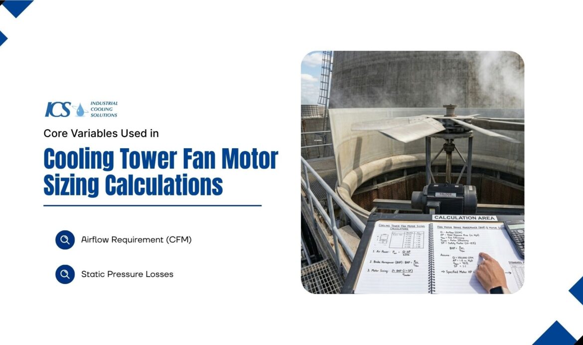
The process of cooling tower fan motor sizing is not random. Engineers calculate power demand using airflow requirements and total system resistance.
The primary variables include:
- Required airflow (CFM)
- Static pressure
- Fan efficiency
- Mechanical drive losses
- Motor service factor
- Tower type
- Operating environment
Each factor directly affects the final horsepower requirement.
Airflow Requirement (CFM)
CFM stands for cubic feet per minute. It represents the amount of air moving through the cooling tower. Higher airflow improves evaporation but requires more fan power.
Large industrial towers may require:
| Cooling Tower Capacity | Typical Airflow Range |
| 50 TR | 30,000–50,000 CFM |
| 100 TR | 60,000–100,000 CFM |
| 250 TR | 150,000–250,000 CFM |
| 500 TR | 300,000–500,000 CFM |
Static Pressure Losses
Internal components create physical restrictions that resist airflow. The fan must overcome these pressure drops to function. You must account for the following restrictions:
- Fill media density
- Drift eliminator profiles
- Inlet louvers
- Fan stack geometry
Dirty fills increase static pressure dramatically over time. Static pressure is typically measured in inches of water gauge (in. WG).
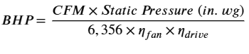
Standard Formula Used to Calculate Cooling Tower Fan Horsepower
Basic Brake Horsepower Formula
Engineers use a standard engineering equation to determine shaft power.
BHP=CFM×Static Pressure / 6356×Fan Efficiency
Where:
- BHP = Brake Horsepower
- CFM = Airflow in cubic feet per minute
- Static Pressure = Inches of water gauge
- Fan Efficiency = Decimal efficiency value
- 6356 = Engineering constant for imperial units
This formula calculates the actual shaft power required by the fan.
Example Calculation
Assume the following operating conditions:
- Airflow = 180,000 CFM
- Static pressure = 2.5 in. WG
- Fan efficiency = 70% (0.70)
The equation becomes:
BHP= 180000×2.5 / 6356×0.70
Calculated result:
- Required BHP ≈ 101 HP
Engineers then apply a safety margin of approximately 10–15%.
Final recommended motor size:
- 125 HP motor
This safety margin protects the motor during:
- Summer peak temperatures
- Fill fouling
- Drift eliminator blockage
- Belt wear
- High humidity conditions
Why Brake Horsepower Alone Is Not Enough
Shaft power, or brake horsepower (BHP), is only the first step in proper cooling tower fan motor sizing. It doesn't account for the total power drawn from the grid, as mechanical losses always increase the required motor size beyond the initial BHP calculation.
Final Motor Sizing Formula with Service Factor
Plant engineers upgrade the basic formula to include realistic conditions.
The service factor usually ranges between 1.1 and 1.25. This multiplier accounts for multiple field variables. These variables include:
- Fill fouling
- Seasonal overload
- Startup stress
- Future degradation
Accounting for Mechanical Transmission Losses
The calculated brake horsepower only represents shaft power. Real-world systems lose energy through mechanical transmission components.
Ignoring these losses leads to severe undersizing.
Direct Drive Systems
Direct drive systems connect the motor directly to the fan shaft.
Characteristics:
- Highest efficiency
- Minimal power loss
- Reduced maintenance
- Lower vibration
Typical efficiency:
- 98–100%
These systems are common in smaller fiberglass cooling towers.
V-Belt Drive Systems
Belt-driven fans experience friction losses during operation.
Typical losses:
- 3–6%
Additional issues include:
- Belt slippage
- Misalignment
- Wear over time
These systems require periodic adjustment as part of the lubrication schedule.
Gearbox Drive Systems
Large industrial cooling towers commonly use gearboxes.
Typical gearbox efficiency:
- 95–98%
Gearbox systems provide:
- Better torque handling
- Lower fan RPM
- Improved large-fan stability
However, gearbox losses must be included in motor sizing calculations.
Step-by-Step Example Calculation for Cooling Tower Fan Motor HP
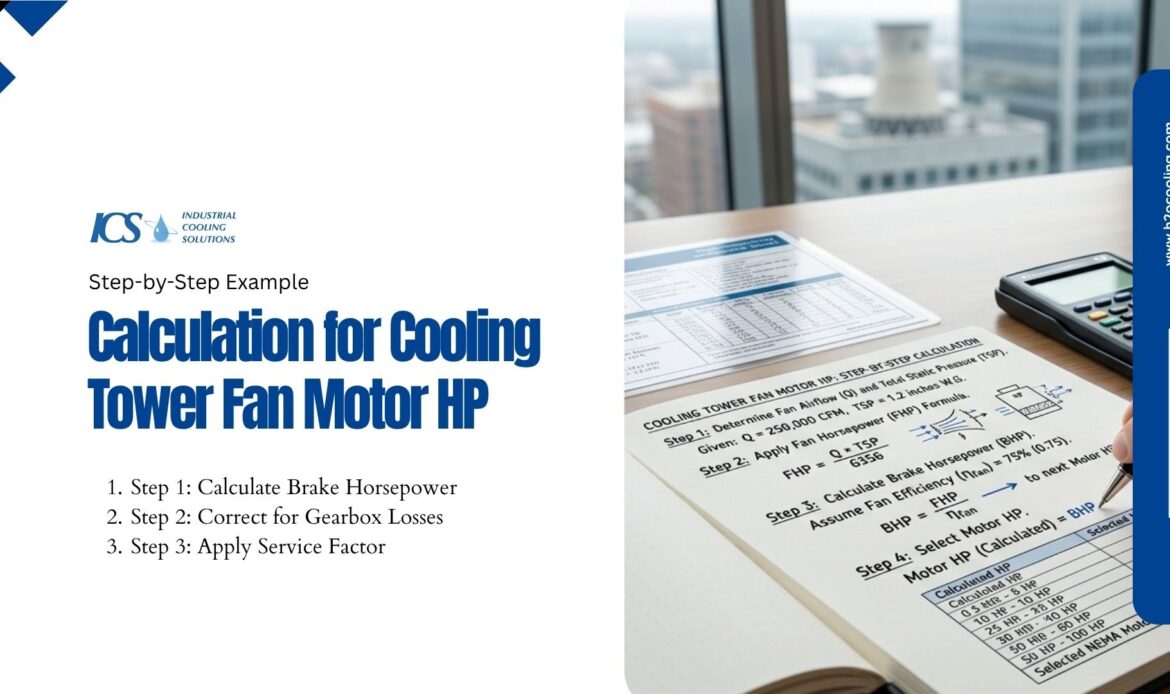
Example Design Conditions
Let's walk through an example calculation for a realistic industrial cooling tower. This will provide a baseline for accurate motor sizing.
- Airflow: 180,000 CFM
- Static Pressure: 1.8 in. WG
- Fan Efficiency: 75%
- Gearbox Efficiency: 96%
- Service Factor: 1.15
Step 1: Calculate Brake Horsepower
Use the actual calculation to find the shaft requirement.
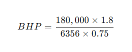
This results in a BHP of 67.97. The fan requires this exact horsepower at the shaft to move the air.
Step 2: Correct for Gearbox Losses
Apply the efficiency correction to find the true power demand. Divide 67.97 by 0.96. The system requires 70.80 HP at the motor shaft.
Step 3: Apply Service Factor
Multiply 70.80 by the 1.15 safety margin. The final calculation equals 81.42 HP.
Engineers always round upward to the next standard motor size. You would select a 100 HP motor for this specific application. Standard motor sizes matter for availability and replacement. The safety margin prevents overload trips during extreme weather.
Typical Cooling Tower Motor Sizing Reference Table
Engineers frequently use rule-of-thumb estimates during preliminary sizing.
| Tower Capacity (TR) | Typical Motor HP | Common Fan RPM | Engineering Insight |
| 50 TR | 3–5 HP | 900–1200 | Small packaged systems |
| 100 TR | 7.5–10 HP | 900–1200 | Standard commercial towers |
| 250 TR | 15–20 HP | 600–900 | Medium industrial applications |
| 500 TR | 30–40 HP | 450–600 | Large process cooling systems |
| 1000+ TR | 50–150+ HP | 300–500 | Heavy industrial duty |
These values vary based on:
- Fill design
- Tower height
- Air density
- Ambient wet bulb temperature
- Fan blade profile
Rule-of-thumb estimates should never replace d
Field Verification: How Engineers Measure Actual Motor HP
Measuring Existing Motor Load in the Field
Electricians measure operational data to verify motor loading. They capture voltage, amperage, and power factor readings directly from the motor control center.
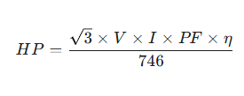
The PF variable stands for power factor. This equation proves useful for troubleshooting overloaded motors in the field.
Warning Signs of Incorrect Motor Sizing
Engineers observe several warning signs during routine inspections. These indicators reveal immediate system problems. You must watch for the following issues:
- High amp draw
- Excessive vibration
- Gearbox overheating
- Unstable fan RPM
- Nuisance breaker trips
Factors That Increase Fan Motor Load Over Time
Fill Fouling
As scale and debris accumulate, they block the air passages within the fill media. This blockage forces the fan to work harder to maintain airflow, which can impact the original cooling tower fan motor sizing calculations.
Drift Eliminator Restriction
Algae growth heavily restricts the drift eliminators over time. This restriction raises the static pressure of the entire tower.
High Wet Bulb Conditions
Dense, humid air requires more mechanical effort to move. Summer conditions naturally increase the load on the motor.
Bearing Wear
Failing bearings introduce extreme mechanical friction into the drivetrain. The motor must draw more amperage to overcome this physical resistance.
Fan Blade Imbalance
Uneven blades cause severe vibration and aerodynamic drag. All these factors increase static pressure or torque demand on the motor.
Undersized vs Correct vs Oversized Motors
| Parameter | Undersized | Correctly Sized | Oversized | Engineering Insight |
| Energy Efficiency | Poor | Optimal | Reduced | Balanced sizing minimizes losses |
| Startup Reliability | Weak | Stable | Excessive current | Large motors stress electrical systems |
| Fan Performance | Inadequate | Accurate | Excessive airflow | Airflow imbalance affects cooling |
| Operating Temperature | High | Stable | Low | Overheating shortens insulation life |
| Equipment Life | Short | Long | Moderate | Correct loading improves reliability |
Best Practices for Cooling Tower Gearbox and Motor Maintenance
Motor reliability depends heavily on preventive maintenance.
Maintain Proper Lubrication Schedule
Routine lubrication protects bearings and gearbox components.
Key practices include:
- Monitoring oil contamination
- Checking vibration trends
- Verifying shaft alignment
- Replacing degraded lubricants
Poor lubrication increases power demand significantly.
Use the Correct Gear Oil Grade
Industrial cooling tower gearboxes commonly use:
- ISO VG 220
- ISO VG 320
The correct gear oil grade depends on:
- Ambient temperature
- Gearbox load
- Manufacturer recommendations
Incorrect viscosity causes overheating and premature wear.
Monitor Oil Change Interval
Ignoring the oil change interval accelerates gearbox failure. Oil degradation leads to:
- Reduced lubrication film strength
- Increased friction
- Bearing damage
- Gear tooth wear
Large industrial towers often require oil analysis every 3–6 months.
Conclusion
Accurate cooling tower fan motor sizing requires rigorous engineering-based calculations. Airflow, static pressure, fan efficiency, and drivetrain losses dictate the required power. Rule-of-thumb estimates help preliminary design phases only. A proper service factor prevents operational overload during extreme weather conditions.
Field verification helps plant managers diagnose existing system problems quickly. Implementing proper motor HP evaluation guarantees your cooling tower operates reliably for decades.
For more on cooling tower fan efficiency, visit h2ocooling.com.
Frequently Asked Questions
How do you calculate cooling tower fan motor horsepower?
You calculate the horsepower by multiplying the airflow by the static pressure. You then divide that number by the fan efficiency and the standard constant.
What is the standard fan horsepower formula?
The standard formula is Brake Horsepower (BHP) equals CFM multiplied by static pressure, divided by 6356 multiplied by fan efficiency.
Why is service factor important in motor sizing?
The service factor provides a safety buffer for the motor. It protects the equipment from overloading due to fouling, wear, or dense air conditions.
How does gearbox efficiency affect motor selection?
Gearboxes consume a small percentage of power through mechanical friction. You must increase the motor size to compensate for this lost power.
Can fan motor HP be verified in the field?
Electricians measure voltage, current, and power factor to calculate actual horsepower. This field data helps verify the original engineering calculations.
What happens if a cooling tower motor is undersized?
An undersized motor draws excessive current and overheats rapidly. The tower fails to move enough air, which ruins the thermal performance of the system.