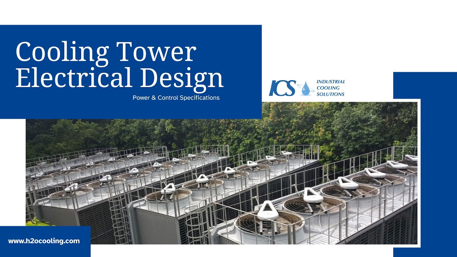
Reliable thermal performance depends on precise engineering, and in industrial settings, the cooling tower electrical design plays a key role in ensuring efficiency and safety. The electrical infrastructure is just as important as the mechanical components; without it, even the most advanced cooling tower won’t function properly.
From power distribution to motor specifications and control panel setups, every detail must align with industrial standards to guarantee seamless operation. In this guide, we’ll break down the essential components of a successful cooling tower electrical design.
Whether you’re planning a new installation or upgrading an existing system, understanding these elements is critical to achieving optimal performance and avoiding costly downtime. Let’s dive into the key factors you need to get it right.
What Is Cooling Tower Electrical Design?
Cooling tower electrical design refers to the specific engineering of power systems and control logic required to operate a cooling tower safely and efficiently. While mechanical design focuses on heat transfer and water flow, electrical design ensures that fans, pumps, and sensors receive the correct power and signals. This distinction is vital for engineers to understand, as the two disciplines must integrate seamlessly.
The scope of this design phase covers several critical areas that determine operational success. Engineers must account for the following elements to create a complete system:
- Power Distribution: The routing of high-voltage power to heavy machinery like pumps and fans.
- Control Systems: The logic and hardware that manage operation based on temperature and demand.
- Protection: Devices installed to prevent damage from overloads, short circuits, or ground faults.
- Wiring and Safety: The physical connection of components adhering to safety codes and standards.
Cooling Tower Power Requirements: Fundamentals
Power Supply Basics
The foundation of any cooling tower electrical design lies in the incoming power supply. Industrial cooling towers typically require a three-phase power supply due to the high load demands of fan and pump motors. Single-phase power is rarely sufficient for anything other than very small, packaged units.
Engineers must select the appropriate voltage and frequency based on the installation location. Common global standards include:
- Voltage Levels: 380V, 400V, 415V, or 480V are standard for three-phase systems.
- Frequency: 50 Hz is standard in Europe and parts of Asia, while 60 Hz is used in North America.
- Stability: The supply must remain stable within a specific tolerance to prevent motor overheating.
Determining Total Power Demand
Accurately determining the total power demand prevents undersized infrastructure and nuisance tripping. This process involves summing the power requirements of every electrical component associated with the cooling tower.
The total demand dictates the size of the main feeder cables and the upstream transformer. You must account for the following loads when calculating total demand:
- Fan Motors: Often the largest continuous load in the system.
- Circulating Pumps: High-demand motors that move water through the tower.
- Basin Heaters: Resistive loads used to prevent freezing during winter shutdowns.
- Control Accessories: Actuators, solenoid valves, and water level sensors.
Electrical Load Calculations Explained
Engineers perform electrical load calculations to size conductors and protection devices correctly. This involves calculating the Root Mean Square (RMS) current drawn by the system under full load conditions. One must also consider the power factor, which represents the efficiency of the power usage in inductive loads like motors.
Key parameters included in these calculations ensure the system handles peak demand without failure. A standard calculation table typically includes:
- Rated Power (kW/HP): The nameplate power rating of the motor.
- Efficiency: The ratio of mechanical output to electrical input.
- Power Factor (PF): The ratio of real power to apparent power.
- Full Load Amps (FLA): The current drawn when the motor operates at rated torque.
Motor Electrical Specifications for Cooling Tower Equipment
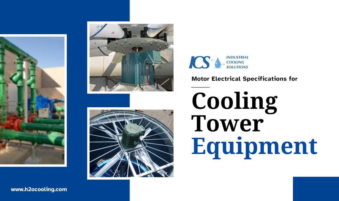
Fan Motor Specifications
The fan motor is the heart of the cooling tower's air movement system and requires specific motor electrical specifications. These motors often operate in harsh, humid environments, necessitating robust insulation and enclosure ratings. Sizing involves selecting the correct horsepower or kilowatt rating to match the fan's aerodynamic load.
When selecting fan motors, consider these critical electrical characteristics:
- Service Factor: A multiplier indicating how much overload the motor can handle temporarily.
- Efficiency Class: IE3 (Premium Efficiency) or IE4 (Super Premium Efficiency) motors reduce energy consumption.
- Enclosure Rating: TEFC (Totally Enclosed Fan Cooled) or TEAO (Totally Enclosed Air Over) are common for moisture protection.
Pump Motor Electrical Specs
Pump motors drive the water circulation and often face different starting characteristics than fan motors. These motors must overcome the inertia of the water column and the friction of the piping system. Consequently, the electrical design must account for high starting currents and torque requirements.
Critical specifications for pump motors include the following elements:
- Voltage and Current: Must match the site supply exactly to prevent winding damage.
- Starting Torque: Sufficient torque is required to accelerate the water to operating speed.
- Duty Cycle: Motors must be rated for continuous (S1) duty if the pumps run non-stop.
Integration with VFD (Variable Frequency Drives)
Variable Frequency Drives (VFDs) provide precise speed control for fans and pumps, improving energy efficiency. By adjusting the frequency of the electrical supply, the VFD allows the motor to run at partial speeds when full cooling capacity is not required. However, VFDs introduce electrical noise that the design must mitigate.
Integrating VFDs requires attention to specific electrical impacts:
- Harmonic Distortion: VFDs create harmonics that can disturb other electrical equipment.
- Cable Selection: Shielded VFD cables prevent electromagnetic interference (EMI).
- Bearing Protection: Shaft grounding rings may be needed to prevent electrical damage to motor bearings.
Control Panel Requirements & Design
Overview of Cooling Tower Control Panel
The control panel serves as the brain of the cooling tower, managing operations based on system feedback. A well-designed panel integrates safety interlocks and control logic to maintain optimal water temperatures. It must withstand the outdoor environment or be housed in a climate-controlled room.
Essential functions of the control logic include:
- Temperature Control: Cycling fans or adjusting VFD speed based on basin water temperature.
- Vibration Monitoring: Shutting down the fan if excessive vibration is detected.
- Low Water Level Protection: Preventing pump cavitation by monitoring basin levels.
Hardware Components
Reliable hardware components are essential for meeting strict control panel requirements. The selection of these components determines the longevity and maintainability of the control system. Engineers typically prefer modular components that allow for easy replacement during maintenance.
Standard control panels contain the following hardware:
- PLC or Relay Logic: The central processor or hardwired logic that executes control decisions.
- Circuit Breakers: Devices that protect individual circuits from overcurrent.
- Contactors: Heavy-duty relays used to switch power to motors.
- Motor Protection Relays: Devices that monitor for overload, phase loss, and unbalance.
Human Machine Interface (HMI)
The Human Machine Interface (HMI) allows operators to interact with the control system efficiently. A clear, intuitive interface reduces the likelihood of operator error and simplifies troubleshooting. Modern HMI panels provide real-time data visualization and alarm history.
Best practices for HMI design focus on clarity and usability:
- Status Visualization: Clear indication of running, stopped, or faulted equipment.
- Alarm Management: Prioritized alarms that guide the operator to the root cause.
- Setpoints: Password-protected access for changing temperature targets and timers.
Wiring Specifications & Installation Standards
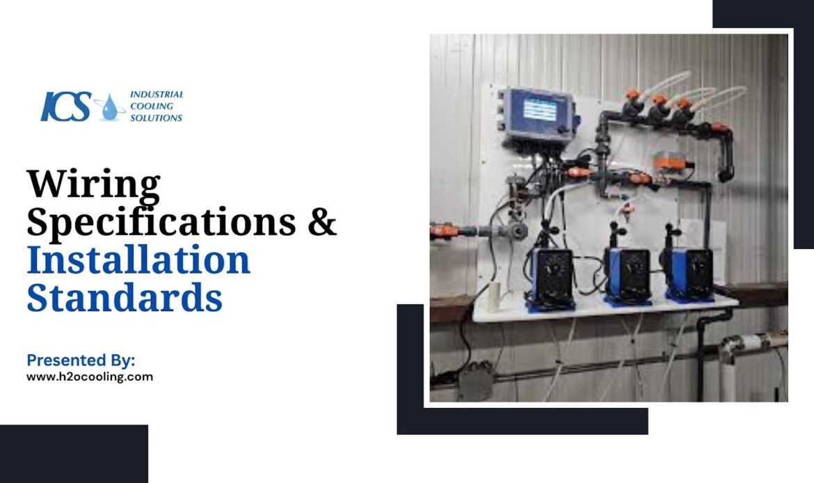
Wire Sizing Calculations
Correct wire sizing prevents overheating and ensures that voltage remains stable at the load. Engineers utilize specific wiring specifications to calculate the required conductor cross-sectional area. This calculation must account for the full load current and the length of the cable run.
Key factors influencing wire sizing include:
- Ampacity: The maximum current a conductor can carry before its temperature exceeds safety limits.
- Voltage Drop: The loss of voltage over long distances, which should typically not exceed 3%.
- Ambient Temperature: Derating factors are applied if cables run through hot environments.
Conductor Type Selection
The material and insulation of the conductors significantly impact the durability of the electrical installation. Copper is the preferred material for industrial cooling towers due to its conductivity and resistance to corrosion. Aluminum may be used for large feeders, but requires special termination techniques.
Selection criteria for conductor types involve:
- Material: Copper is the standard for control and motor wiring due to its superior conductivity and corrosion resistance. While aluminum is a lighter and often more cost-effective option for large feeders, it requires specialized termination techniques and careful installation to prevent oxidation at connection points.
- Insulation: THHN/THWN-2 rated insulation is common for its high resistance to heat, moisture, and chemicals, making it suitable for the demanding conditions of a cooling tower. XHHW-2 insulation is another robust alternative, offering excellent durability and a higher temperature rating.
- Stranding: Stranded wire is preferred over solid wire because its flexibility simplifies installation in tight spaces and provides superior resistance to mechanical stress and vibration, which are common in industrial settings.
Raceway & Conduit Requirements
Raceways and conduits protect conductors from physical damage and environmental exposure. In cooling tower applications, these pathways must resist corrosion caused by moisture and chemical treatment agents. Proper support and routing prevent sagging and water accumulation inside the conduit.
Conduit specifications must address the following installation details:
- Material: PVC-coated rigid steel or intermediate metal conduit (IMC) is often specified for corrosion resistance.
- Sizing: Conduits must not be overfilled, allowing for heat dissipation and ease of pulling wires.
- Drainage: Low points in the conduit run should have drain fittings to release condensation.
Grounding and Bonding
Proper grounding is non-negotiable for personnel safety and equipment protection. It provides a low-resistance path for fault currents and stabilizes voltage levels during normal operation. Bonding connects all metallic non-current-carrying parts to the grounding system, preventing shock hazards.
Effective grounding strategies include:
- Equipment Grounding Conductor: A dedicated wire run with the power conductors to ground the motor frame.
- Equipotential Bonding: Connecting the tower structure, handrails, and motor frames to a common ground grid.
- VFD Grounding: Special high-frequency grounding techniques to mitigate noise from drives.
Protective Devices & Safety Requirements
Circuit Protection
Circuit protection devices isolate faults to prevent fire and equipment destruction. Fuses and circuit breakers serve as the primary defense against short circuits and sustained overloads. The selection between fuses and breakers depends on the required interrupting capacity and maintenance preferences.
The protection hierarchy typically includes:
- Short Circuit Protection: Instantaneous tripping to disconnect high-fault currents.
- Overload Protection: Thermal elements that disconnect power during prolonged minor overcurrent events.
- Phase Failure Protection: Monitors that trip the circuit if a phase is lost to prevent motor damage.
Surge Protection
Cooling towers are often the highest structures in a facility, making them vulnerable to lightning strikes. Furthermore, switching transients from large motors can damage sensitive control electronics. Surge Protective Devices (SPDs) clamp voltage spikes to safe levels.
Implementation of surge protection involves:
- SPD Placement: Installed at the main distribution panel and the local control panel.
- Lightning Protection: Air terminals and down conductors are installed on the tower structure itself.
- Transient Voltage Suppression: Protecting PLCs and sensors from internal grid fluctuations.
Safety Standards
Compliance with safety standards protects workers and ensures legal operation. The cooling tower electrical design must adhere to the National Electrical Code (NEC), IEC standards, or local regulations. These codes dictate minimum requirements for wiring methods, clearances, and disconnects.
Crucial safety protocols include:
- Lockout/Tagout (LOTO): Local disconnect switches must accept padlocks to isolate power during maintenance.
- Arc Flash Safety: Panels must be labeled with arc flash boundaries and PPE requirements.
- Emergency Stops: Accessible buttons to stop the equipment immediately in an emergency.
Troubleshooting Common Electrical Issues
Even with a robust design, electrical issues can arise during the cooling tower's operational life. A systematic troubleshooting approach reduces downtime and identifies the root cause quickly. Maintenance teams rely on accurate design documentation to diagnose these faults.
Common issues encountered in the field include:
- Repeated Motor Tripping: Often caused by overload, phase imbalance, or a degraded motor winding.
- Excessive Voltage Drop: Indicates undersized cables or loose connections creating high resistance.
- Control Panel Faults: Failed relays or PLC modules that prevent the system from executing logic.
- Communication Errors: Noise interference or wiring faults disrupting data to the BMS.
- Overheating Components: Caused by poor ventilation, excessive current, or faulty equipment.
- Unexpected Power Loss: Often due to circuit breaker trips, power supply issues, or damaged wiring.
Conclusion
A successful cooling tower project relies on the seamless integration of mechanical engineering and effective Cooling Tower Electrical Design. By strictly adhering to principles regarding electrical load calculations and wiring specifications, engineers ensure the system operates reliably for decades. From selecting the right motor electrical specifications to designing robust control panel requirements, every detail contributes to safety and efficiency.
Always prioritize safety by following established codes and standards. A well-designed electrical system not only powers the equipment but also protects the facility and its personnel from harm. Learn more and discover the perfect cooling solution at h2ocooling.com!
Frequently Asked Questions
What voltage should a cooling tower electrical system be designed for?
The voltage depends on the local industrial supply and the size of the motors. Common voltages are 480V/3-phase/60Hz in the US and 400V/3-phase/50Hz in Europe and Asia.
How do I calculate the electrical load for a cooling tower?
To perform electrical load calculations, sum the full load amps (FLA) of all fans, pumps, heaters, and controls. Apply a safety factor (typically 125%) to the largest motor and 100% to the rest to size the main feeder.
What are the essentials of control panel design?
A control panel must include circuit protection, motor starters (or VFDs), a PLC or relay logic for automation, and an HMI or pilot lights for operator feedback. It must also meet control panel requirements for environmental protection (NEMA/IP ratings).
How do I choose the right motor specs?
Select motors based on the load (HP/kW), environmental conditions (TEFC/TEAO enclosures), efficiency requirements (IE3/IE4), and duty cycle. Ensure the voltage and frequency match the site supply.
What wiring standards should be followed?
Follow the National Electrical Code (NEC) in the US or IEC 60364 internationally. This includes correct wiring specifications for conductor sizing, grounding, and conduit selection.